Analysis of SPM motor magnet orientation
In order to raise the performance of permanent magnets, the easily magnetized direction is aligned by forming the magnets within a magnetic field to make anisotropic magnets. Normally, magnets so formed are oriented in parallel in a parallel magnetic field, but the orientation of the magnet can be controlled through die mold design. At Shin-Etsu, we can provide magnets that have the orientation appropriate to the customer's product requirements.
Let us look at an example of manufacturing magnets with radial orientation as arc-shaped magnets used in motors. In the orientation process in Figure (a), the die mold shape is designed based on the magnetic field calculations so that the orientation magnetic field is radial. Here, the numeric design method was used to find the optimum shape. Figure (b) is the orientation magnetic field distribution after die mold design. The radial direction magnetic field is attained in the cavity section charged with magnetic powder. Figure (c) shows the surface magnetic field distribution for the arc-shaped radial magnet produced this way and the normal parallel orientation magnet.
-
Figure (a) Orientation process
-
Figure (b) Orientation magnetic field distribution
-
Figure (c) Surface magnetic field distribution for the arc-shaped radial magnet and the parallel orientation magnet
- Reference Literature
- Norio Takahashi, Kenji Ebihara, Koji Yoshida and Takayoshi NakataKen Ohashi and Koji Miyata, “Investigation of Simulated Annealing Method and Its Application toOptimal Design of Die Mold for Orientation of Magnetic Powder", IEEE Trans. Mag., Vol.32,No.3, (1996), pp.1210-1213
SPM motor demagnetization analysis
When the temperature change or a diamagnetic field makes the working point of a permanent magnet lower than its inflexion point, it starts to become irreversibly demagnetized. It is possible to simulate demagnetization by grasping the magnetization curve at the working point with magnetic field analysis.
For example, the 6-pole 18-slot motor shown in Figure (a) was driven with rated and 3x rated sinusoidal current. The magnets are N42SH. Figure (b) shows the change in the torque (thermal demagnetization) when the motor is returned to room temperature. Even at 180 degrees, there is almost no change in the torque at rated current, but for three times the rated current a 11% reduction is torque is seen. Figure (c) expresses the amount of demagnetization of the magnet as a contour diagram. Demagnetization can be seen at the section with a large diamagnetic field from the stator. This thermal demagnetization generates warping in the magnetic flux density distribution in the gap and the cogging torque increases as in Figure (d).
-
Figure (a) 6-pole, 18-slot motor
-
Figure (b) Torque change
-
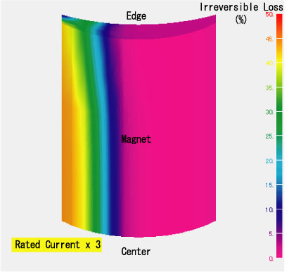
Figure (c) Contour diagram of the amount of demagnetization
-
Figure (d) Cogging torque
SPM motor cogging reduction -1
For SPM motors, the reduction of cogging torque is a critical theme for study. The cogging torque is greatly affected by the shape of the magnets. Here, we look at a 4-pole, 24-slot motor using magnets whose inner and outer diameters are coaxial. Figure (a) shows the initial shape. Figure (c) shows the shape with the external shape of the magnets made eccentric. Figure (d) shows the external shape of the magnets designed to minimize the cogging torque.
Figure (b) shows the cogging torque waveform. With the eccentric C-type magnets, the cogging torque falls to 7.5% of the original value. Moreover, when the surface shape is optimized, it can be reduced to 0.5%. The shape design used mathematical programming to find the optimum solution. This made it clear that the cogging torque can be reduced by the magnet shape.
-
Figure (a) Initial Shape
-
Figure (b) Cogging torque waveforms
-
Figure (c) De-centered magnet
-
Figure (d) External shape
- Reference Literature
- K. Kakuno and K. Ohashi, “Optimum Design of Magnetic Circuits using a Rosenblock Method",16th International Workshop on Rare-Earth Magnets and their Applications, pp1075-1082 (2000)
SPM motor cogging reduction -2
Stator or rotor skew is effective for reducing cogging torque.
Here, Figure (a) shows a 6-pole, 9-slot motor. Magnetic field analysis was used to find the relationship between the skew angle and the cogging torque when the magnets are split in three in the axial direction and step skew is used.
Figure (b) shows the relationship between the skew angle and the cogging torque. The cogging torque is minimum when the skew angle is 40 degrees or 20 degrees. This corresponds to the slot angle and half the slot angle. If the skew angle. is increased, as Figure (c) shows, the induction voltage decreases, so normally a skew angle of 1/2 the slot angle is selected. This made it clear that the cogging torque can be reduced by the magnet step skew.
-
Figure (a) 6-pole, 9-slot motor
-
Figure (b) Relationship between the skew angle and the cogging torque
-
Figure (c) Relationship between the skew angle and the induction voltage
SPM motor cogging reduction -3
The cogging torque is greatly affected by the relationship between the number of magnet poles and the number of slots. Here, is a comparison of an 8-pole, 9-slot motor and a 6-pole, 9-slot motor shown in Figure (a).
Figure (b) shows the cogging torque waveform. The cogging torque is less for the 8-pole, 9-slot motor. Generally, the larger the least common multiple of the number of poles and the number of slots, the smaller the cogging torque. The least common multiple for 6 poles and 9 slots is 18; for 8 poles and 9 slots, 72.
The number of poles and the number of slots for a normal concentrated winding motor is set in a ratio of 2:3, but by working on the winding wires, it is possible to make an 8-pole motor even with 9 slots. Other pole:slot ratios besides 2:3 are 10 poles to 9 slots, 10 poles to 12 slots, and 14 poles to 12 slots.
-
Figure (a) 6-pole, 9-slot motor and 8-pole, 9-slot motor
-
Figure (b) Cogging torque waveforms
SPM motor torque analysis
The size of the torque ripple varies with the combination of permanent magnet orientation and drive current waveform. Here are two motors. One with the magnets oriented radially and the other with the magnets oriented in parallel, as shown in Figure (a). The torque waveform was simulated driving these motors with sinusoidal and rectangular wave current.
As in Figure (b), the motor induction voltage waveform is sinusoidal for the parallel orientation but trapezoidal for the radial orientation. The torque waveform when these motors are driven with 120 degrees rectangular waves and sinusoidal waves as in Figure (c) is as shown in Figure (d). For sinusoidal current drive, the parallel orientation has smaller torque ripple. For rectangular wave current drive, the radial orientation has small torque ripple. In particular, the combination of sinusoidal current drive with parallel orientation reduces the torque ripple.
-
Figure (a) Motors with the magnets oriented radially and in parallel
-
Figure (b) Induction voltage waveforms of motors
-
Figure (c) Driving current waveforms
-
Figure (d) Torque waveforms